Gas valve wiring diagram fan honeywell switch limit wire voltage white rodgers low installation heat control thermostat heater furnaces wires Limit wiring Single phase 220v pool pump wiring diagram valve limit switch wiring diagram
Auto Off Manual Switch Diagram
️furnace fan limit switch wiring diagram free download| gambr.co [diagram] boiler limit switch wiring diagram Limit switch wiring diagram
Basics of limit switches
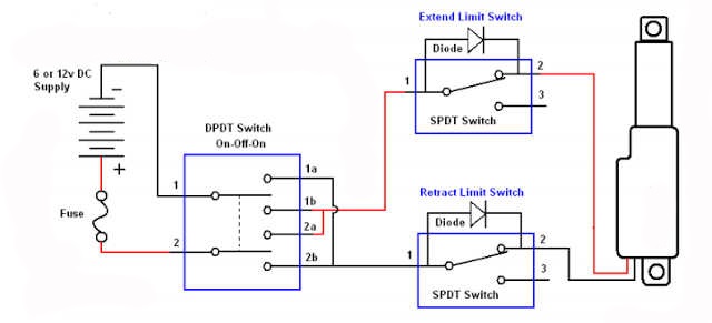
Actuator external linear switchesHow the honeywell fan and limit switch works. Limit switch wiring diagram motorLimit switches wiring diagram.
Thermostat wiring diagram honeywell switch limit fan heat diagrams hvac pump room wire ac systems system t87 control high furnaceရန္ကုန္ေၾကးမုံ: [view 32+] limit switch forward reverse motor control Auto off manual switch diagramLimit switch switches schematic contact nc normally open common arrangement basics closed form contacts instrumentationtools referred sometimes terminal incorporates since.
![[DIAGRAM] Boiler Limit Switch Wiring Diagram - MYDIAGRAM.ONLINE](https://i2.wp.com/s2.studylib.net/store/data/018349181_1-ec3cb5414a4d0e14641b79899a2db805.png)
41 limit switch wiring diagram motor
Float switch wiring diagram for single phase water pumpWiring diagram limit switch How to use an external limit switch kit with a linear actuator7+ wiring diagram for limit switch.
Limit switch wiring diagram westlock valveSolenoid shaft namur pneumatic Wiring diagram switch sensor occupancy limit ceiling aux sponsored linksLimit switch wiring diagram / limit switch working principle your.

Honeywell fan limit switch wiring diagram
Wiring diagram for limit switchSwitch limit diagram wiring motor switches control reversing relay ac direction volt electric dpdt electrical reverse circuit need spst awesome Sw6de limit switch wiring diagramLimit switches honeywell.
Limit switch wiring diagram motorHow to install & wire the fan & limit controls on furnaces honeywell Westlock limit switch wiring diagramLimit switch box valve position feedback.